How to add, change, and remove an entity?
CAD VCL provides a wide range of methods to work with drawing entities.
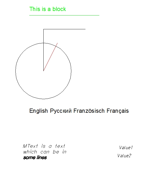
For example, let's load the Entities.dxf file and create a procedure to add, change, and remove entities. You can find this file in the CAD VCL package.

As you can see, the file extension is DXF.
- Add
DXF,DXFConv, andsgConststo theusessection. Create a new procedure to add, change, and remove entities.
uses DXF, DXFConv, sgConsts, sgFunction;
...

type

  TForm1 = class(TForm)
    FImage: TImage;

 ...

implementation

procedure TForm1.AddChangeDeleteClick(ASender: TObject);
- Declare the local variable
vDrawingand specifyTsgDXFImageas its type.
More information about formats and their corresponding classes
| Class | File format |
|---|---|
| TsgHPGLImage | PLT, HGL, HG, HPG, PLO, HP, HP1, HP2, HP3, HPGL, HPGL2, HPP, GL, GL2, PRN, SPL, RTL, PCL |
| TsgSVGImage | SVG, SVGZ |
| TsgDXFImage | DXF |
| TsgCADDXFImage | DXF |
| TsgDWFImage | DWF |
| TsgDWGImage | DWG |
| TsgCGMImage | CGM |
Declare the entity you want to add. For example, let's add an ellipse. Declare vEllipse and specify TsgDXFEllipse as its type. Do the same with the vEntity variable of the TsgDXFEntity type.
var
  vDrawing: TsgDXFImage;
  vEllipse: TsgDXFEllipse;
  vEntity: TsgDXFEntity;
- Create an instance of the
TsgDXFImageobject. Remember to use thetry...finallyconstruct to avoid memory leaks. Then call theLoadFromFilemethod of this class. The parameter of this method is a DXF file.
begin
  vDrawing := TsgDXFImage.Create;
  try
    vDrawing.LoadFromFile('Entities.dxf');
- The
Entities[const AIndex: Integer]: TsgDXFEntityproperty lists all the entities of the CAD file. TheIndexparameter indicates the index of the object and it counts from 0.
Use theColorCADproperty to change color and theLineWeightproperty to change lineweight (values are measured in millimeters) of the second entity.
  vDrawing.CurrentLayout.Entities[1].ColorCAD:= MakeColorCAD(acIndexColor, 5);
  vDrawing.CurrentLayout.Entities[1].LineWeight := 2;
- Assign the
vDrawing.CurrentLayout.Entities[2]value to thevEntityvariable. Remove the third entity using the following conditional statement.
  vEntity := vDrawing.CurrentLayout.Entities[2];
  if vDrawing.CurrentLayout.RemoveEntity(vEntity) then  FreeAndNil(vEntity);
- Create the ellipse entity. Add the entity to the current layout. Set two points. Points have three floating values:
x, y, z. Finally, set its radius and ratio. Use theMakeColorCADmethod to change theColorCADproperty.
  vEllipse:= TsgDXFEllipse.Create;
  vDrawing.CurrentLayout.AddEntity(vEllipse);
  vEllipse.Point := MakeFPoint(10, 10, 0);
  vEllipse.EndPoint := MakeFPoint(15, 15, 0);
  vEllipse.Radius := 3;
  vEllipse.Ratio := 1.5;
  vEllipse.ColorCAD:= MakeColorCAD(acIndexColor, 5);
- The
Loadsmethod fills the internal data of the entity to prepare it for drawing.
vDrawing.Converter.Loads(vEllipse);
- Finally, write the code to recalculate drawing extents. Draw the entity on the canvas with
StretchDraw, and then destroy thevDrawingobject. Dimensions of the drawing should not be equal to zero.
    vDrawing.GetExtents;
    FImage.Canvas.StretchDraw(Rect(0, 0,
    Round(vDrawing.Width * FImage.Height / vDrawing.Height), FImage.Height), vDrawing);
  finally
    vDrawing.Free();
  end;
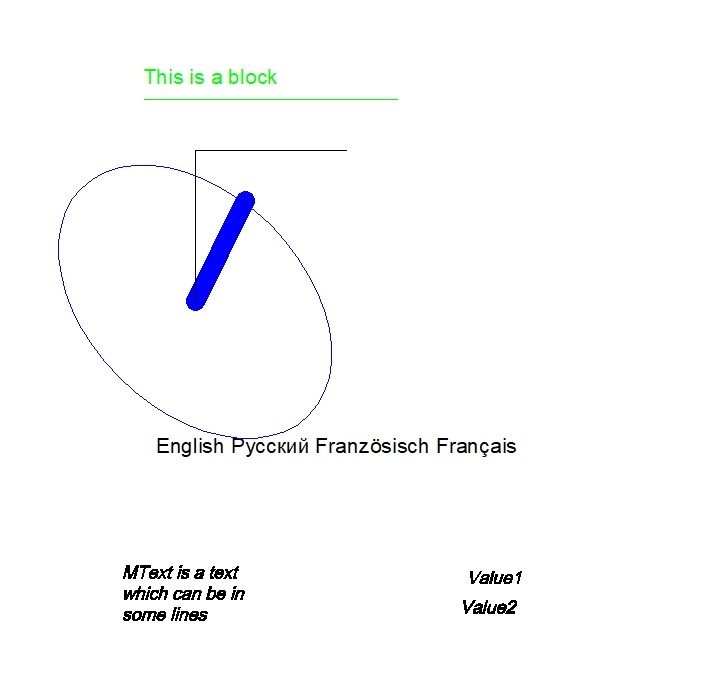
You have created the procedure to add, change, and remove entities.
The following picture illustrates the result of your procedure.

The full code listing.
uses DXF, DXFConv, sgConsts, sgFunction;
...

type

  TForm1 = class(TForm)
    FImage: TImage;

 ...

implementation

procedure TForm1.AddChangeRemoveClick(ASender: TObject);

var
  vDrawing: TsgDXFImage;
  vEllipse: TsgDXFEllipse;
  vEntity:  TsgDXFEntity;

begin
  vDrawing := TsgDXFImage.Create();
  try
    vDrawing.LoadFromFile('Entities.dxf');
    vDrawing.CurrentLayout.Entities[1].Color := clBlue; // changing properties
    vDrawing.CurrentLayout.Entities[1].LineWeight := 5;
    vEntity := vDrawing.CurrentLayout.Entities[2];
    if vDrawing.CurrentLayout.RemoveEntity(vEntity) then  FreeAndNil(vEntity); // deleting the third entity
    vEllipse:= TsgDXFEllipse.Create; // creating a new ellipse
    vDrawing.CurrentLayout.AddEntity(vEllipse);
    vEllipse.Point := MakeFPoint(10, 10, 0);
    vEllipse.EndPoint := MakeFPoint(15, 15, 0);
    vEllipse.Radius := 3;
    vEllipse.Ratio := 1.5;
    vEllipse.ColorCAD:= MakeColorCAD(acIndexColor, 5);
    vDrawing.Converter.Loads(vEllipse);
    vDrawing.GetExtents;
    FImage.Canvas.StretchDraw(Rect(0, 0,
    Round(vDrawing.Width * FImage.Height / vDrawing.Height), FImage.Height), vDrawing);
  finally
    vDrawing.Free();
  end;
end;