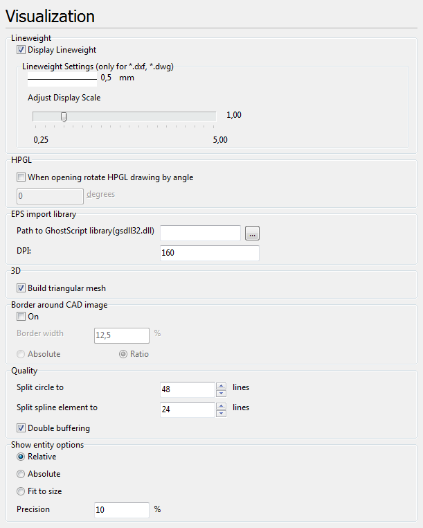
The tab contains the settings for the visualization of CAD files. It allows to set the splitting parameters of a circle and spline and some other parameters.
Lineweight
The section Lineweight defines lineweight parameters. A one pixel wide line corresponds to the lineweight value of "0,00 mm". The lineweight of other lines in pixels is set in proportion to their precise values.
•Display Lineweight - if checked the lineweight of all the entities of a vector image is displayed according to the specified value of the property Lineweight. If the option is switched off the lines are displayed one pixel wide. The corresponding icon on the toolbar is ![]() .
.
•Adjust display scale - use this option for increasing or decreasing entities' lineweight scale factor. It doesn't affect the lineweight when printing but an additional print option allows to take it into account.
HPGL
When opening rotate HPGL drawing by angle - sets the necessary angle value for automatic rotation of Hewlett-Packard HPGL files when they are loaded. By default the option is off.
EPS import library
The section contains information about the third-party library GhostScript(gsdll32.dll), with the help of which viewing of PDF and EPS files is performed in CADEditorX User Interface. The path to the library is entered automatically after its installation and the following opening of a PDF or EPS file. The library can be loaded at
http://sourceforge.net/projects/ghostscript/
http://www.ghostscript.com/
•Path to GhostScript library - determines the path to the GhostScript library.
•DPI - determines the resolution of your computer screen. It is characterized by the number of pixels per inch.
3D
•The Extended structure option turns on the display of the extended structure for 3D files. If the option is switched off, the structure will be limited to 3D Solid.
If you have an opened 3D file, refresh the structure after switching the option.
•The Show edge after load option controls the edge display after opening a 3D file. If this option is on, 3D model edges are displayed and the Edges button is active on the 3D Viewer tab once you open a 3D file.
•Anti-aliasing mode. It turns on anti-aliasing in 3D modes.
Quality
The section Quality contains three options which set the quality of display of vector elements and allow to use double buffering when viewing graphics files.
•Automatic regeneration. The option sets the dynamic split of circles and arcs to pieces (lines) while their visualization. The number of lines changes the display scale changes.
•High-quality automatic regeneration. The option sets the split of circles and arcs to the maximum available number of pieces (lines).
•Custom regeneration. The option allows setting the number of pieces (lines) into which circles and splines must be split.
oSplit circle to allows setting up the number of lines the arcs would be split up to. The greater the number of lines, the smoother the appearance of the circle or arc is. The setting affects the display of the drawing, printing and saving it into raster formats. That is why if you need to get a raster image of a high quality it is necessary to enter the maximal split number before export.
oSplit spline element to allows likewise setting up the number of lines which splines would be split up to. The more lines set the better the quality of the drawing is.
•Double buffering determines whether the image is rendered directly to the window or painted to an in-memory bitmap first. It reduces the amount of flickers when the image repaints, but is more memory intensive and can affect performance as all the drawing operations are first executed in the memory and then on the screen.
Go to CADEditorX