This tab contains settings which are used for measuring tools such as Distance, Polyline Length and Area. These settings do not influence the view of the dimension values and other similar information appearing in the drawing. They allow to set the scale factor and the units in which the measurement of the drawing must be performed. These settings aren't saved into the drawing file and are cleared after closing the drawing.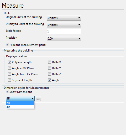
Units
Settings of measurement results precision, scale and displayed units of measurement. Settings of this section affect all measurement tools in 2D and 3D modes.
•Original units of the drawing. Sets units of measurement in which the drawing is made. Used in 2D mode only.
•Displayed units of the drawing. Sets units of measurement in which measurement results must be displayed in the current file. If the displayed units are the same as the original ones the scale factor will be equal to 1. Used in 2D mode only.
•Scale factor. Defines custom unit's multiplier.
For instance: loaded drawing's units are millimeters. You want to have coordinates in centimeters when using measuring tools. Set Scale factor equal 0.1. Now all measuring values will be in centimeters.
Conversion of CAD units to the viewed values occurs by the following formula:
"Original units" * "Scale factor" * k = "Displayed units",
where k - is correspondence coefficient between two unit types - "Original units" and "Displayed units".
If Scale factor <> 1, k takes value 1 and "Displayed units" are turned to Unitless.
•Precision. Sets the number of the decimal digits for the values obtained after measuring. The option can be changed in the context menu of the Measure panel during measurement.
•Hide measurement panel. Regulate the appearance or disappearance of the Measure panel after the measurements have been made. Check the box if you prefer the Measure panel to stay visible.
Measuring the polyline
Selection of parameters for meausuring with the help of the Polyline Length tool, that is available in the 2D mode.
▪Polyline length is the total length of the polyline outline.
▪Angle in XY Plane is an angle between the vector of the measured segment and the X-axis in the XY plane.
▪Angle from XY Plane is an angle between the vector of the measured segment of the polyline outline and the Y-axis in the XY plane.
▪Segment length is the distance between the start and end points of the polyline outline segment.
▪Delta X is the value of the projection of the vector of the measured segment of the broken outline on the X-axis.
▪Delta Y is the value of the projection of the vector of the measured segment of the broken outline on the Y-axis.
▪Delta Z is the value of the projection of the vector of the measured segment of the broken outline on the Z-axis.
▪Angle is the angle contained by two adjacent segments of the polyline outline. The angle value for the first polyline outline segment is equal to 0 degrees.
Dimension Styles for Measurements
Settings of the dimension lines form that are showed while measuring drawings elements with the help of any measurement tool.
▪Show dimensions allows showing or hiding dimension lines when measuring elements of the drawing in the 2D mode.
▪2D [...]. When the [...] button is clicked, the Dimension Style dialogue box opens and the user can set the visual style of dimension lines displayed when the drawing is measured in the 2D mode.
▪3D [...]. When the [...] button is clicked, the Dimension Style dialogue box opens and the user can set dimension lines size and text height as well as change color of the dimension lines displayed when the drawing is measured in the 3D mode.
Go to ABViewer