The Properties button shows or hides the panel Properties which is usually located in the left part of the screen - on the left of the drawing area.
Quick Access Panel: ![]()
Ribbon: Advanced -> Window -> Properties
Menu: View -> Properties
Hotkey: F4
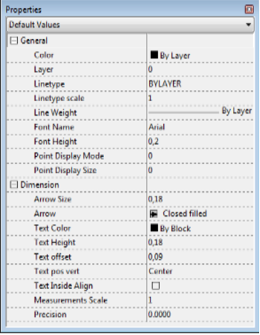
The Properties panel gives access to
othe properties of the currently selected entities;
odefault properties which will be applied by default to each new entity created.
It is a dockable, resizable window that contains a list of entities' properties and allows changing them. Double click on the panel's title bar displays the Properties panel in a separate window that you can position anywhere you like on your desktop. The Properties panel is available in Editor and Redline modes.
The Properties panel allows setting the necessary default properties. These properties will be applied to every new entity by default. Default properties are grouped into two categories:
•General - properties for all entities.
•Dimension - properties for the Dimension entities.
Default Values
The drop-down menu under the word Properties:
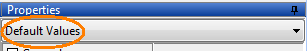
shows the current contents of the Properties panel - i.e what properties are currently shown in this panel. Thus the drop-down menu will contain the name of the selected entity (if any entity or entities are selected) or if no entity is selected the panel will show Default Values which means the properties that are attributed to any new elements of the drawing:
For example:
 - none of entities are selected. Properties panel shows currently default values applied to new entities. - none of entities are selected. Properties panel shows currently default values applied to new entities. - a Polyline is selected. - a Polyline is selected. - 3 Polylines are selected. - 3 Polylines are selected. - 2 different entities are selected. - 2 different entities are selected. |
You can set the default properties the way you need. They will be applied to every entity you create as default values. Default properties are grouped into two categories:
•General - properties for all entities.
•Dimension - properties for the Dimension entities.
General
Color |
Defines entities' color. By default the value is By layer. In ABViewer the color model RGB is used.
|
|
Layer |
Allows to change the layer for the selected entities or to set a layer current when no element is selected. For HPGL/2 files this list views available pens. When it is necessary to create a new layer (pen), use menu item Viewer Tab ->CAD Image -> Layers. |
|
Linetype |
Allows to change the linetype for the selected entities or to set a linetype current when no element is selected, i.e. all the entities to be created will have this linetype. The used linetypes are stored in the drawing file. It is impossible to add a new linetype. ABViewer has a standard set of linetypes that are available for a new drawing. When editing a drawing that was created not in ABViewer only the used in this file linetypes are available. |
|
Linetype scale |
Allows to change the linetype scale for the selected entities or to set a linetype scale current when no element is selected, i.e. all the entities to be created will have this linetype scale. This parameter is used when viewing line with non CONTINUOS linetype. It defines multiplayer which is used to count a distance between dashes in the line. The linetype scale can be the same for all the objects or set for each entity separately. By default it is equal to 1.
|
|
Line Weight |
Allows changing line weight for the selected entities and SHX fonts. Line weight must be equal to the standard values. When entering an arbitrary value it is changed to the nearest standard value. You can turn the function of showing the lines according to their lineweight on or off. Each lineweight value corresponds to a number of pixels on the screen. The number of these pixels isn't changed while scaling in the program window. The scale of lineweighht display on the screen is set in the Visualization tab of the Options window.
|
|
Font Name |
Allows defining a font for a new multiline text, single line text or attribute definition. |
|
Text Height |
Allows defining the symbols' height. Height is set in drawing units. Symbols of multiline text may have different height. The text height can be an integer number or a decimal fraction. A separator is a comma. |
|
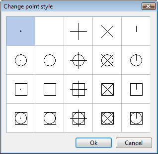
Point Display Mode |
Allows to specify the view of a point entity. You can't enter the value from the keyboard. To change the view of the point press [...]. A corresponding window will open.
|
|
Point Display Size |
Defining the size of all the points in the drawing. |
Arrow Size |
Defines the arrow size of dimension and leader entities. |
|||||||||||||||||||||||||||||||||||||||||
Dimension Style |
Sets the dimension style that will be used by default when adding dimensions and leaders to a drawing. For every element the style can be set separately. To create and edit dimension styles use the command Dimension Styles. |
|||||||||||||||||||||||||||||||||||||||||
Arrow 2 Leader Arrow |
Defines the arrows' view of dimension and leader entities. The left and the right arrows of dimension entities may have different views.
|
|||||||||||||||||||||||||||||||||||||||||
Text Color |
Defines dimensions' text color. By default the value is By layer. In ABViewer the color model RGB is used.
|
|||||||||||||||||||||||||||||||||||||||||
Text Height |
Defines dimension's text height. It can be an integer number or a decimal fraction with a comma as a separator. |
|||||||||||||||||||||||||||||||||||||||||
Text offset |
Defines dimension's text offset. |
|||||||||||||||||||||||||||||||||||||||||
Text pos vert |
Defines a placement of dimension's text on vertical axis relatively to dimension line.
|
|||||||||||||||||||||||||||||||||||||||||
Text Inside Align |
Defines the text alignment along the dimension lines. |
|||||||||||||||||||||||||||||||||||||||||
Measurements Scale |
Defines scale parameter which is used for linear dimensions. It is not recommended to change the default value - 1. |
|||||||||||||||||||||||||||||||||||||||||
Precision |
Defines the number of characters after the comma in the dimension text. |


Note: all changes are applied for the current file only.
Go to ABViewer